Product details
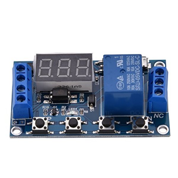
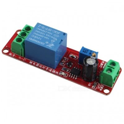
Multi-Function Delay Timer Module Switch Control Relay Cycle Timer is 6-30V 1-Channel Delay Power Relay Module with Onboard Adjustable Timing Cycle Switches with Digital LED display It is mostly used in Home Automation Delay Timer Control Switch Module Timer Controller. The Module operates at Operating voltage range of 6-30V, also it supports micro USB 5.0V power supply. Output capability Can control the device within DC 30V 5A or AC 220V 5A. It can be applied to many fields as there is a wide range of application.
Features:
- Wide voltage supply (6-30V) supports micro USB 5V power supply, which is very convenient to use
- The interface is clear and simple, powerful, easy to understand, and almost meets all your needs
- One-button emergency stop function (STOP key), with reverse polarity protection, reverse connection does not burn
- Added sleep mode, enabled, no operation within 5 minutes, automatically turn off the monitor; any key wakes up
- Can set different OP, CL, LOP parameters, these parameters are independent of each other, respectively, saved
- All setting parameters are automatically saved and saved
Specifications:
- Dimension: 6.2 * 3.8 * 1.7cm
- Operating voltage: DC 6V-30V (supports micro USB 5V power supply)
- Trigger signal source: high-level trigger (3V-24V) signal ground and system to improve the system’s anti-jamming capability (also short-circuit altogether)
- Output capability: it can control the device within DC 30V 5A or within AC 220V 5A
- Quiescent current: 20mA
- Operating current: 50mA
- Service life: more than 100,000 times
- Working temperature: -40°C-85°C
- With optocoupler isolation, enhanced anti-jamming capability, industrial grade circuit board, set parameters for memory after power failure.
Operation Mode:
- P1: Trigger signal, the relay is on “OP” time, and then disconnect; Within the “OP” time, proceed as follows.
- P1.1: the signal is triggered again, invalid.
- P1.2: the signal is triggered again, re-clocking.
- P1.3: Signal has triggered again, the relay is disconnected, stop the clock.
- P-2: Trigger signal, after the “CL” time is off, the “OP” time is on. When the timing is completed, the replay will be disconnected.
- P3.1: Trigger signal, after the “OP” time is on, the “CL” time is off, then cycle the above actions. If trigger signal within the loop, the relay will be disconnected and stop the clock. The number of cycles ( “LOP “) can be set.
- P3.2: No need to trigger the signal after powering up, the “OP” time is on, the “CL” time is off, then cycle the above actions; The number of cycles ( “LOP “) can be set.
- P-4: Signal holding function. If the signal is triggered, timing is cleared, the relay remains on; when the signal disappears, the relay will be off when the “OP” time is over; if another signal is triggered during timing, timing will be cleared.
How to choose the timing range:
After setting the parameter value in the mode selection interface, press the STOP button to select the timing range.
- XXX. The decimal point is in one place, the time range is: 1 second ~ 999 seconds
- XX.X decimal point in ten, timing range: 0.1 seconds to 99.9 seconds
- XXX decimal point is fully illuminated, timing range: 1 minute ~ 999 minutes
How to set parameters:
1. First determine the relay operating mode
2. According to the working mode of the relay, in the main interface (when the module is powered on, it will flash the current working mode (default P1.1 mode), and then enter the main interface,) “Press and hold the SET button for 2 seconds to release “. Enter the mode selection interface, select the mode to be set (P1.1~P-4) by pressing the UP and DOWN keys;
3. After selecting the mode to be set (for example, P3.2), short-press the SET button to set the corresponding parameter, then the parameter to be set will blink (OP conduction time, CL disconnection time, LOP cycle times (“– – “On behalf of infinite number of cycles)), through UP, DOWN adjust the parameter value, support long press (fast increase or decrease) and short press (increase or decrease 1 unit); after setting the parameter value, press STOP key shortly To select the decimal point position, select the time range (the corresponding time 0.1 seconds ~ 999 minutes); short press the SET button to set the next parameter of the current mode, the process is the same as above;
4. After setting the parameters of the selected mode, press and hold the SET button for 2 seconds to release it. The currently set mode will flash, and then return to the main interface. Setting the parameters is successful. Main interface: “000” (no decimal point) is displayed when the relay is not working. The relay is in working state with a decimal point;
5. Mode selection interface: long press the SET key to enter, after setting is complete, long press the SET key to exit, back to the main interface.
Note: The relay output is a passive contact and has no live output to control the on-off of a line.

Mode Select Interface:
Press and hold the SET key to enter; after setting, long press the SET button back on main interface
Activate Relay Mode:
- NO: PO in power over time, the relay can be connected
- OFF: relay is not allowed to connect, when in the off state
Sleep Mode:
- C-P Sleep mode: within 5 minutes, no operation; nixie tube will close auto display, and a function program well
Note:
1. Press and hold the STOP button for 2 seconds can achieve change from C-P to O-d; Current state will flash and then return to the main interface
2. The relay contact is passive and electricity production; 1 channel has the control function on / off
Package Included:
- 1 X Multi-Function Delay Timer Module Switch Control Relay Cycle Timer

There are no reviews yet.